
Series vs Parallel Circuits: Rules and Calculator
Series and parallel circuits compared: how current, voltage and resistance behave, total resistance formulas, a free calculator, worked examples and real uses.
Key takeaways
- In series, the current is the same everywhere, voltages add up and resistances add: R = R₁ + R₂ + …
- In parallel, each branch gets the full voltage, currents add up and 1/R = 1/R₁ + 1/R₂ + …
- The total resistance in parallel is always less than the smallest single resistor.
On this page
Components can be connected in two basic ways. In a series circuit, they’re joined end to end in a single loop, so the same current flows through each one and the supply voltage is shared between them. In a parallel circuit, each component sits on its own branch across the supply, so each gets the full voltage and the total current is split between branches. Most real circuits, including the wiring in your home, use parallel connections so that each device works independently.
The rules at a glance
| Series | Parallel | |
|---|---|---|
| Current | The same through every component | Splits between branches; branch currents add up to the total |
| Voltage | Shared; the voltages across components add up to the supply | The same across every branch |
| Total resistance | R = R₁ + R₂ + R₃ … | 1/R = 1/R₁ + 1/R₂ + 1/R₃ … |
| Adding a resistor | Increases total resistance | Decreases total resistance |
| If one component fails | The whole circuit stops | Other branches keep working |
Total resistance calculator
Enter resistor values separated by commas. Add a supply voltage to see currents and voltages.
Series and parallel resistance calculator
Enter at least one resistance.
Worked example: series
A 6 V battery is connected to a 2 Ω and a 4 Ω resistor in series.
- Total resistance: R = 2 + 4 = 6 Ω.
- Current: I = V ÷ R = 6 ÷ 6 = 1 A, the same through both resistors.
- Voltage across each: V = I × R, so 1 × 2 = 2 V and 1 × 4 = 4 V. Together they add up to the 6 V supply.
Worked example: parallel
The same resistors are connected in parallel across 6 V.
- Total resistance: 1/R = 1/2 + 1/4 = 3/4, so R = 4/3 ≈ 1.33 Ω.
- Each branch has the full 6 V.
- Branch currents: 6 ÷ 2 = 3 A and 6 ÷ 4 = 1.5 A.
- Total current: 3 + 1.5 = 4.5 A, which matches 6 ÷ 1.33.
Both examples use Ohm’s law, V = I × R. Our Ohm’s law calculator handles single components.
Useful shortcuts
- Two resistors in parallel: R = (R₁ × R₂) ÷ (R₁ + R₂). For 2 Ω and 4 Ω: 8 ÷ 6 ≈ 1.33 Ω.
- Identical resistors in parallel: divide one resistor’s value by how many there are. Three 12 Ω resistors give 4 Ω.
- Identical resistors in series: multiply by the number of resistors.
- Sanity check: a parallel total must be smaller than the smallest resistor in the group.
Bulbs in series and parallel
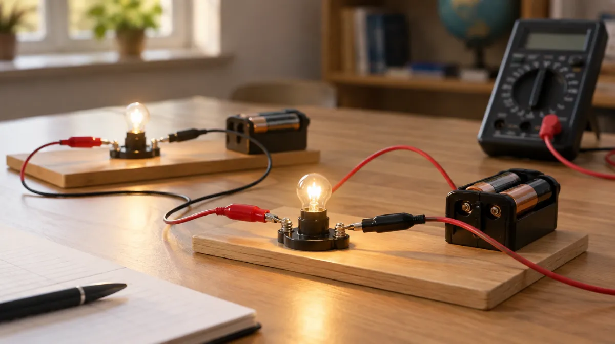
Two identical bulbs in series share the voltage, so each glows more dimly than a single bulb would, and if one fails, both go out. In parallel, each bulb gets the full voltage and glows at normal brightness, but together they draw twice the current, so the battery runs down faster. Old strings of Christmas lights were wired in series, which is why one broken bulb could stop the whole string.
Cells and batteries
Cells in series add their voltages: two 1.5 V cells make 3 V. Identical cells in parallel keep the same voltage but can supply current for longer. This is why battery packs combine both arrangements.
Where you see each type
| Series | Parallel |
|---|---|
| Simple switches controlling a circuit | Household sockets and lights |
| Fuses and circuit breakers, which must carry the full current | Car lighting circuits |
| Some decorative light strings | Most electronic devices’ internal supply rails |
| Cells in a torch | Solar panel strings combined into arrays |
Household wiring is parallel so every appliance gets the full mains voltage and can be switched on or off independently. Fuses and breakers sit in series with each circuit so they can cut the current if it gets too high.
Measuring current and voltage
- Ammeters measure current and are connected in series, so the current flows through them.
- Voltmeters measure voltage and are connected in parallel across the component.
Power in circuits
The power used by each component is P = V × I, or P = I² × R. In the series example above, the 4 Ω resistor uses 4 V × 1 A = 4 W; in parallel, it uses 6 V × 1.5 A = 9 W. See work, energy and power for the energy side, and the physics formula sheet for all the equations in one place.
Common mistakes
- Adding parallel resistances directly. Use the reciprocal formula, and remember to flip the answer at the end.
- Forgetting the final reciprocal: 1/R = 0.75 means R = 1.33 Ω, not 0.75 Ω.
- Assuming current is used up in a series circuit. It isn’t; the same current flows all the way round.
- Mixing milliamps and amps, or kilohms and ohms.
Frequently asked questions
Why is the total resistance lower in parallel?
Adding a branch gives the current another path, like adding lanes to a road, so more current can flow for the same voltage.
Are houses wired in series or parallel?
In parallel, so each appliance gets the full mains voltage and works independently.
What happens if one bulb breaks in a parallel circuit?
Only that branch stops. The other bulbs stay lit because their branches are still complete.
Sources

Every article is edited by a human and checked against our editorial policy. Spotted a mistake? Tell us.